ZEBRA Elastomeric Connectors |
ZEBRA Elastomeric Electronic Connectors are a comprehensive group of high performance interconnect devices with applications throughout the entire field of electronics. With the expansion of micro-electronics and miniaturization of all products, the same high reliability must be maintained.
ZEBRA Elastomeric Connectors are an obvious choice. And one which offers a variety of alternatives based on the primary design objectives. Some of the more important considerations are:
- High Density; increased number of I/O’s
- Low resistance, high current capacity
- Low insertion force, low compression force
- Redundant contact engagement
- High electrical and mechanical reliability
- Chemical stability, degradation resistance
- Cost-effectiveness, ease of assembly
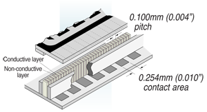
ZEBRA Elastomeric Connectors have alternating conductive and non-conductive layers. See diagram below. The conductive layers are oriented vertically in the thickness direction, making contact from top to bottom.
 |
 |
|
Typical ZEBRA Connector interface between two contact areas such as, PCB to LCD, or PCB to PCB. |
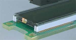
ZEBRA® Silver Connector in medical instrument display. |
All styles offer redundant contact depending on the pitch of the conductive layers, some as small as 0.05 mm centerline (see drawing above).
- LCD and EL displays
- Flex circuit-to-board
- Board-to-board
- Burn-in sockets
- Chip-to-board
- Miniature and low profile
- Memory cards interconnect - general electronics
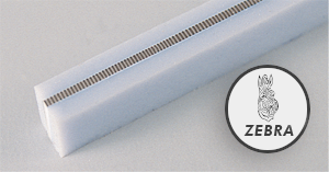
Each of the styles is also available with outer support sections along the entire length on one or both sides (except Series 8000). The support is available in sponge or solid silicone rubber, and creates a larger width area. This eliminates the need for a holder while still allowing a very low compression force during deflection.
 |
 |
|
Typical ZEBRA Connector with optional silicone rubber self-support sections oneach side. |
High strength bonding unitizes layers into one rugged body. |
ZEBRA Connector Technical DataThe six ZEBRA Elastomeric Connector designs below are detailed in their dimensional and performance characteristics. Follow the general guidelines to determine the design characteristics most suitable for your application. See following pages for detailed characteristics. |
 |
| The photo enlargements demonstrate the multiple contact points per circuit conductor pad for typical ZEBRA² connector designs. |
| Name | Application Guidelines | Typical Products |
|---|---|---|
| Carbon | Economical general use with contact pitches at 140, 240 or 500 per inch | LCD’s for aerospace, aircraft, military, meters, instruments, cameras |
| Silver | 300m Acurrent carrying capacity, rugged long-life aging with contact pitches at 240 per inch | |
| Gold 8000 | Zero insertion force,tight pitch,low compression force, very low resistance, very high current carrying capacity; contact pitches at 100, 133, 166 per inch | Electroluminescent displays, component-to-board, burn-insockets, PCB to PCB, chip on glass, LCD’s, chip on foil, COF’s |
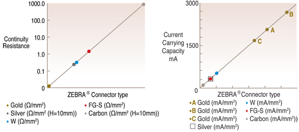
Typical Performance Characteristics:
Side Support or Insulation Barrier:
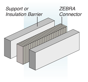 |
Drawing on the left shows side support or insulation on one or both sides, or one of each. Various materials are available from the minimum insulating barrier of 0.05mm to support layers of up to 1.5mm. Support layers can be soft silicone rubber, or medium and soft silicone sponge. Recommended height is twice the width for minimum force deflection. |
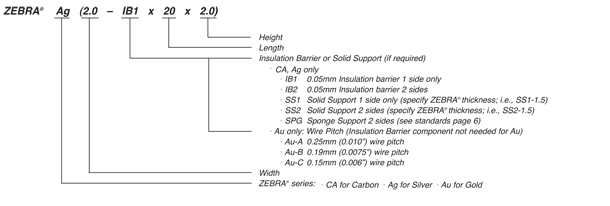
Part Number and Nomenclature:
To specify a connector to your exact requirements, substitute the metric measurements for width, length and height according to instructions below; example part# Ag(2.0 IB1 x 20 x 2.0)-U;
